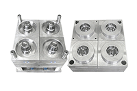
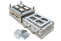
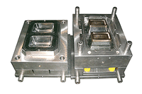
The thin wall mould daopts fully automatic stripper systec;
no-guide pinBK all around loacting system;
The molding cycle pershot only needs 3.2sec;
the movment of PPmaterial is 1/350;
The produces wall thickness is unifomity and clear;
It is safe for packing food, medicine and medicaltreatmnet device.
For aggressive thin wall mould, we use steel harder than P20, especially
when high wear and erosion are expected. H-13 and S136,DIN1.2316
steels have been successful in gate inserts
Molrt release.
Venting is critical and can be facd interlocks sometimes can stave
off flexing and misalignment. so we use thin wall mould's cores
to telescope into the cavity ,which can help reduce core shifting
and breakage.
We use heavier support plates (often 50 to 75 mm thick) with support
pillars (typically preloaded 0.12 mm.) under the cavities and sprue.
Use more and larger ejector pins than with conventional molds to
reduce pin pushing.
Strategic placement of sleeve and blade knockouts are used by us.
No. 2 diamond polish on cores and ribs can eliminate problems of
part sticking. thin wall mould's surface treatments, such as nickel-PTFE
can also improve pailitated with vented core pins and ejector pins,
as well as venting along up to 28% of the parting line around the
part. Vents are typically 0.02 to 0.03 mm. deep and 5 to 1mm wide.
While not usually necessary, some processors have sealed the parting
line with an O-ring in order to pull a vacuum on the cavity for
quick gas evacuation.
With higher injection speeds, gates larger than the nominal walls
help reduce material shear and gate wear and help prevent freeze-off
before good packing is achieved.
Gate inserts with a Rockwell (Rc) hardness greater than 55 are typically
used to withstand high injection pressures.
When gating directly onto a thin wall with a sprue, pinpoint, or
hot-drop, use gate wells to reduce stress at the gate, aid filling,
and reduce part damage when degating from thin wall mould.
Hot manifolds can help reduce pressure loss in runner systems, but
they require at least 0.5-in.-diam. inner passages with no sharp
corners or dead zones. Manifolds should have external, not internal,
heaters. Valve gates, if used, must be non-restrictive and built
to take high pressure.
.In addition, cooling of the cores and cavities is more critical
and challenging in thin-wall applications. Two important guidelines
adopted are: Non-looping cooling lines should usually be located
directly in the core and cavity blocks to help keep the mold surface
temperature as consistent as possible. Instead of decreasing coolant
temperature to maintain the desired steel temperature, it is generally
better to increase the amount of coolant flow through the thin wall
mould. As a rule of thumb, the difference in temperature between
the delivery coolant and return coolant should be no more than 5°
to 10° F.
|

 Arabic
 Spanish
 German
 Japanese
 Russian
 French